Construction » Building Points
Dave Webb
The following article is a description of how I went about building the points for the "Boulder Creek Tramway", a 71/4" gauge, 1/3rd scale miniature of a typical Australian 2 foot gauge bush railway being built in Howden, just south of Hobart in Tasmania.
Now I'm no expert and I'm not trying to say for one second that this is the only way, the best way, or even the right way, of building points but this is how I built them and they work perfectly for me!
The first thing to do is to decide on the radius of your points. It is desirable to make the radius as large as possible, however the larger the radius is, the longer the points need to be, and the heavier and more difficult they are going to be to handle and move into position.
The minimum radius of the Boulder Creek Tramway is 14 metres so that is the radius I have used to build all of my points.
A set of points will use approximately three times there own length in rail plus the ties (the small metal sleepers that the rail is welded to before being screwed onto the timber sleepers) and of course the timber sleepers. I use 32mm x 10mm flat bar for the rail on the Boulder Creek Tramway and this is welded to 20mm x 5mm flat bar for the ties. These are screwed to 90mm x 45mm treated pine sleepers at 250mm centres.
For the first set of points I built, I marked them out on the workshop floor. This was not the most practical way of building them however, and when the time came to build a further five sets I needed a better plan.
I drew a scale drawing of the points using a CAD program, but you could just as easily draw a scale drawing using a pencil and paper. I found this convenient for getting the lengths of each piece of rail so I could pre-cut everything ready for assembly.
Once I had the pre-cut lengths, I drilled the ends of the rails that would later need fish plates bolted to them to join the points to the rest of the track.
I then set about tapering the point blades and machining the taper on the two inner rails that meet at the frog. This can be done with an angle grinder if you don't have a milling machine but milling is a far better way to do the job. I only mill the taper about 10mm deep on the point blades which maintains the strength in the blade. This is deeper than the allowable wheel flange depth anyway so removing more material is "pointless"! Only machine the taper over about half the length of the point blade as well. More on this later.
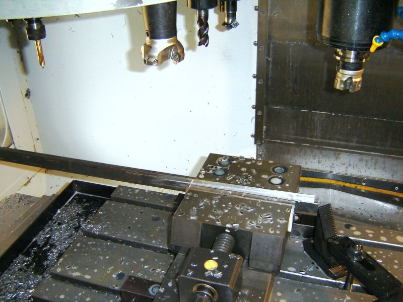
Once I have milled the blades I set about rolling the curved sections of rail. Rolling makes setting the point out so much easier and helps to maintain a smooth curve through the point without ending up with odd shaped bends and kinks in your rail. If you don't have any rolling equipment it would be wothwhile making a simple roller for the job. Alternatively, take all of your pre-cut lengths to a sheet metal works for rolling to the correct radius of your points.
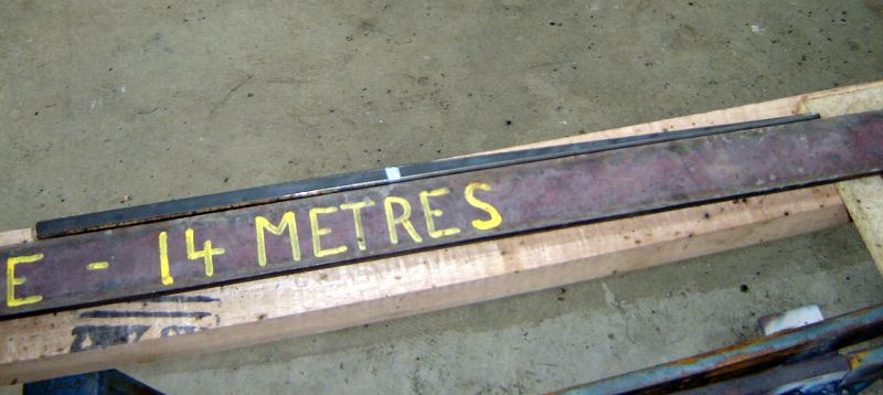
While you rolling rail, roll a radius gauge which is long enough to cover at least 3/4 of the length of your points. I used a piece of 50mm x 5mm flat and rolled it on its edge to make a 14 metre radius gauge.
After rolling the rail sections, weld the two short tapered sections (one rolled and one straight) together to form part of the frog. Use your CAD or scale drawing to find the dimension to set the distance these rails should be apart at the ends before welding them.

The next step is to cut the check rails and frogs where they are bent. I cut about 2/3 of the way through the rail on the side that is to be on the inside of the bend, and then bend the rail be placing the short end in the vice and pulling the cut gap closed. Make sure you don't cut it all the way through!
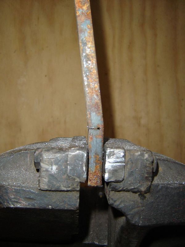
You are now at the stage of assembly and the best place to start is by laying the outer straight rail and the pre-welded frog section on a flat work area and gauging the short straight section as shown in the photo below.
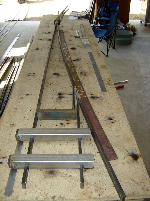
Using your radius gauge, lay the curved section shown below and make sure the gap between the straight rail and the check rail is correct, and that there is a smooth transition through the frog. Also check that the gap at the point blade end of the curved rail is correct and that the gauge meets the straight rail at the far end of the gauge and follows the curved rail through the full length of the points. I clamp spacer blocks into the gap between the check rail and frog and into the gap at the far end of the curved rail to make sure the gaps are correct before welding.
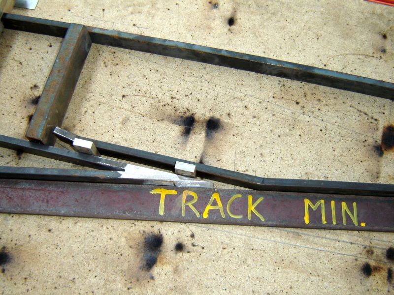

The ties can now be tack welded to the rails to hold the assembly in place. You can weld the ties either on top or under your assembly depending on whether you are building a left or right handed point.
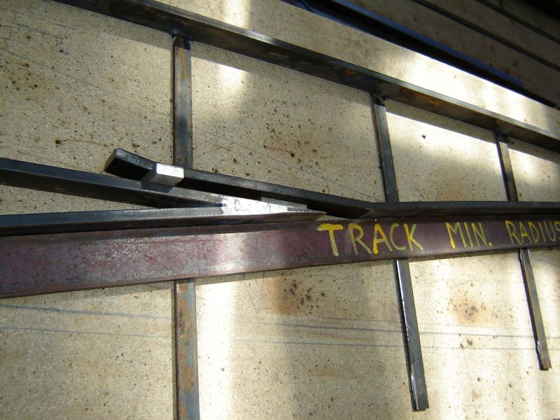
Using a piece of flat steel as a straight edge inserted between the short straight rail and check rail, fit the next length of straight rail which isalso the check rail on the other side of the frog as shown. Also clamp a gauge block in at the far other end to ensure the gauge at the other end is correct, and check the gauge off the outer straight rail at each tie as you weld the inner rail in position.
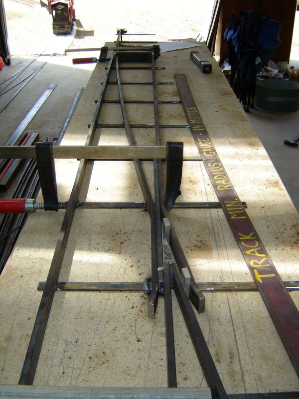
You can now fit the outer curved rail using gauge blocks at each end, and again checking the gauge off the inner curved rail at each tie. The inner curved rail should be correct as you have set it from your radius gauge.
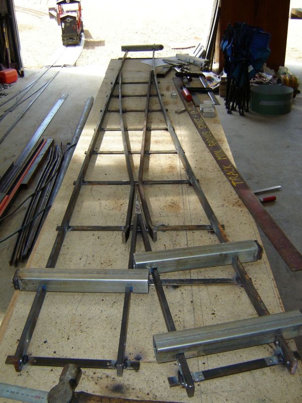
You can now fit the check rails to your points. Again, use small spacer blocks clamped in position to set the gap while welding the check rails in place.
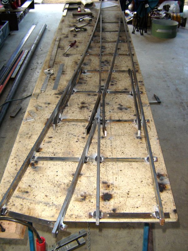
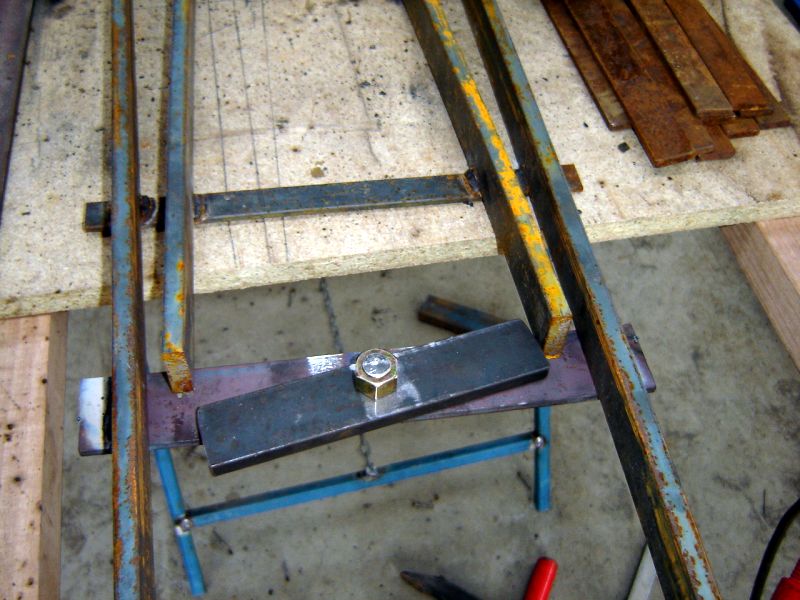
The next step is to make and fit the pivot for the point blades. I have used 40mm x 5mm flat for the bottom plate and 32mm x 10mm for the top pivoting section with a 12mm blot welded through the bottom plate. Do the bolt up finger tight and then back it off just far enough to allow the top piece to pivot freely. Fit a lock nut, or peen the bolt over to prevent it coming loose.
Going back to the milling of the point blades you will recall that I machined mine on a straight taper about half the length of the blades. You can see in the photo below, there is a chalk line on the point blade where the milled section tapers out to nothing around half the way along the blade. You will need to bend the blade here so that the blade itself is not straight but the rail head where the wheel runs is straight. Looking along the point blade you can see that the blade is bent in the middle but where the wheel runs is straight. You can check this with a straight edge when bending the blade. I do it this way so I donít have to taper the full length of the point blades which would make them thinner over there entire length and more likely to bend in service.

You can now lay the straight point blade in position and check it lines up with the straight inner rail at the pivot and the outer curved rail where they meet.
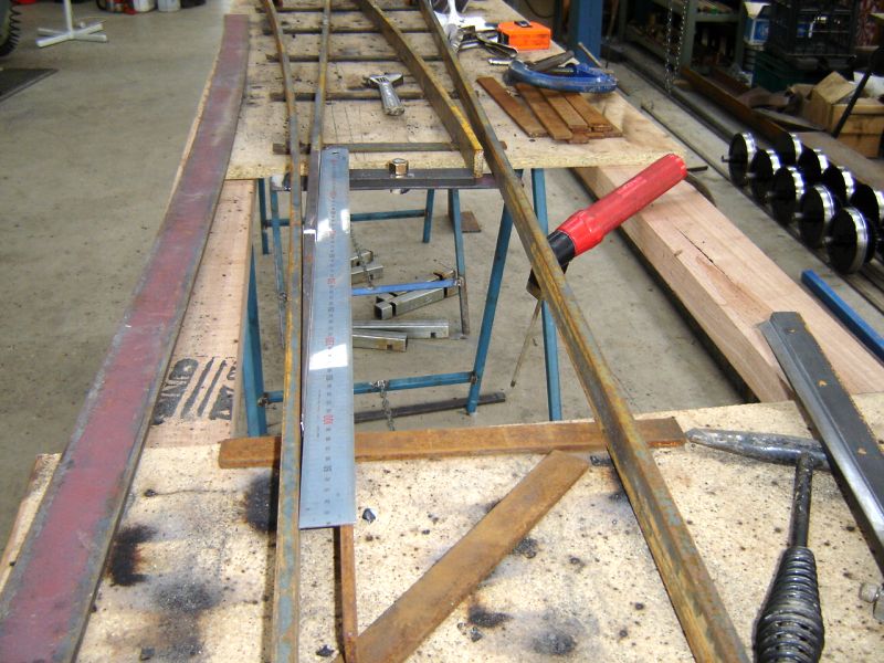
When happy with the alignment you can weld the blade to the pivot. Follow the same procedure with the curved blade except bend the blade on the chalk line to match your radius gauge rather than the straight edge.
Fit the curved blade in position and check the alignment with your radius gauge at both the pivot end and the other end where the curved blade meets the outer straight rail.

Again, when happy with the alignment weld the blade to the pivot. Make sure before welding that you ďopenĒ the blade on the other side and allow enough space between the open blade and the running rail for the wheel flange. You can now fit the sliding tie at the tapered end of the point blades. I use a slightly heavier tie than the ones used on the track for this as it is not secured to a timber sleeper. I also fit another tie each side of the sliding tie, again out of the heavier steel. These two ties have to support the point blades when the train runs across the point.

The points are now just about finished and all that is left to do is to screw the sleepers to the points and fit them in position on the track for testing!
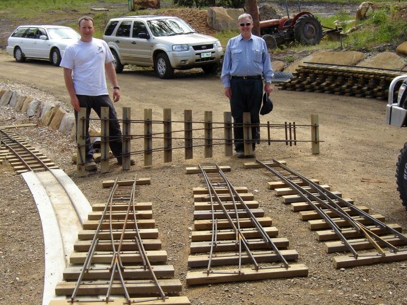
Thatís me on the left with one of my trusty offsiders on the right.
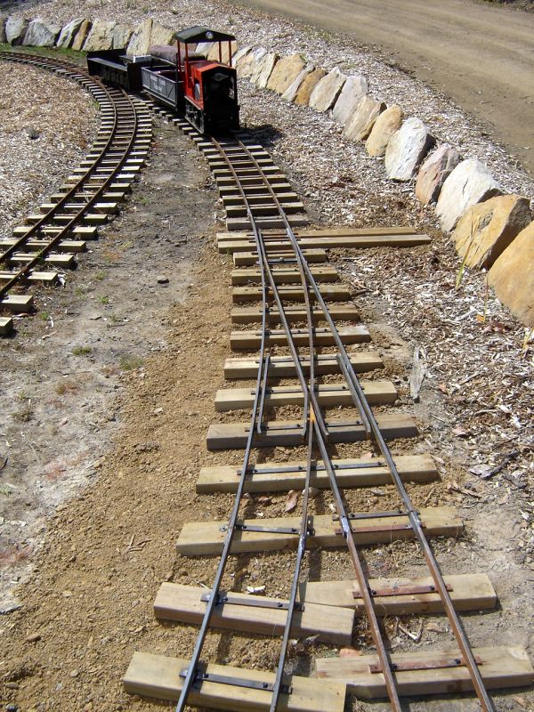
The first set of points in position on the Boulder Creek Tramway with the test train in the background. Note the longer sleepers at either side of the sliding tie. These are to allow a throwover to be fitted. Make these long enough so you can fit your throwover far enough away from the track that they will not obstruct passing trains!
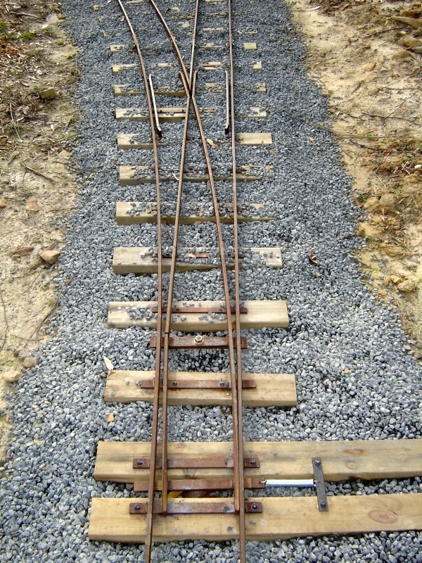
Since writing the above article on points construction a common question has been asked of me about the operation of my spring loaded points. As the saying goes, "a picture speaks a thousand words" and the following picture clearly shows the addition of an extension spring which automatically returns the points to their correct position once a train has run through them. The spring loaded points have been fitted to the entrance to my reversing loops, to the passing loops, and to the points in the reversing wye allowing continuous running without the driver having to get off the train to switch points.
I did find initially that I had set the spring pressure too tight causing very light carriages to run over the blade rather than pushing them open against the spring causing the occasional derailments. Since backing the tension off to a bare minimum, there have not been any problems. General maintenance requires a drop of oil under the blade where they slide on the ties every now and then as well as clearing out any foliage that occasionally blows in and around the point blades.
|
Updated: 23 Dec 2012 21 |
Text and photos Copyright © 2008-2019 Dave Webb, All rights reserved. Email author |
Created by deeja Nov 2009