Dave Webb
The following article is a description of how I have modified automotive alternators for use as a controllable power source to drive the electric traction motors used in miniature locomotives I have built for my railway:- the Boulder Creek Tramway.
I am not an electrician nor am I an electrical engineer, electronics technician, etc. I am a fitter and machinist by trade so I will do the best I can to explain what I have done to make this system work for my locos.
Automotive alternators are readily available, and are capable of producing high currents. Alternators are a little different to generators as they produce 3-phase AC power (at a relatively high frequency), and this is converted to DC by a built-in rectifier (Generators produce DC directly). Refer to Fig. 01 below for a typical schematic diagram.
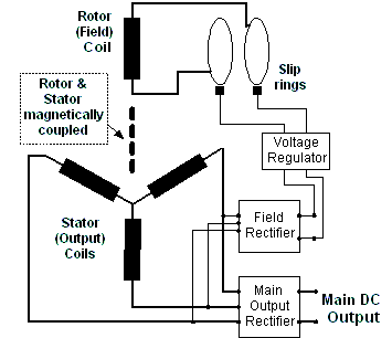
Modern alternators often have an internal voltage regulator which regulates the alternators main output to the vehicles battery voltage. The rotor in an alternator contains a field coil or field windings, which are powered by the regulator via the brushes. This produces a magnetic field which generates the voltage in the main stator windings. By varying the rotor field voltage the regulator controls the alternator main output voltage. Detailed descriptions on how alternators function can be found on the internet, and these sites:- Understanding Alternators, Alternator Secrets and Understanding the Alternator give good explanations.
I have built four 71/4" gauge petrol/electric locos, all of which use an engine driven alternator to power the traction motor. This setup has proven to be both very reliable and very simple. The issue I initially had was how to control the speed of the traction motor fitted to my locos. I use high power series wound 24 volt DC motors used in electric winches for my traction motors and these are capable of drawing a huge amount of current.
I could not come up with a suitable and cost effective electronic speed control that was capable of handling the amount of current required by these motors so I had to find a more suitable way. It is possible to build a control using electronics alone but I don't have the knowledge to build such a control and I would have needed the engine and alternator to supply the power to run it from anyway. I know of people who have used commercially available MOSFET type speed controllers and have found that they get very hot due to the high current drawn by the traction motors. Some have found that they get so hot that solder joints have melted or the MOSFETs have burnt out.
The advantage of the setup I use is that the speed control only needs to handle the 2~3 amps required by the alternator field windings, not the huge current required by the traction motor. I have done this by using the several methods described below.
In my first loco, I initially I used a rotary switch running a series of resistors, but later converted to a simple electronic voltage control unit. Both methods are successful, however the electronic control is easier to build and wire up, and gives a smoother control over the loco power and speed.
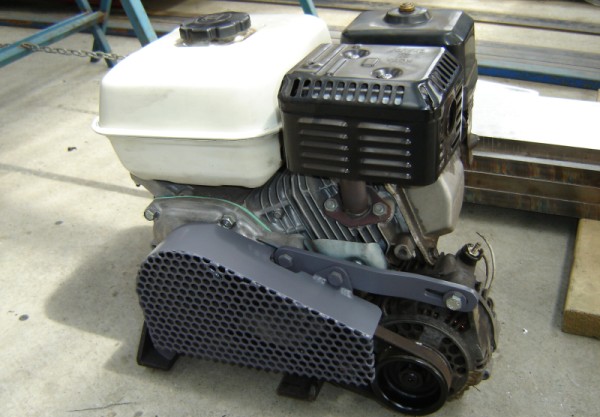
Pictured above in Fig.02 is the engine alternator unit fitted to my smaller loco. This is a 5.5HP Honda engine driving a 12 volt 100 amp alternator with the internal regulator disabled and the speed control, or more correctly, the "voltage control unit" connected to the alternator. The alternator main positive output is wired directly to the traction motor via a reversing relay. This relay must be able to carry the maximum current that the alternator is rated at. The reversing relays I use are for an electric anchor winch or a 4WD recovery winch. They are more than capable of handling the current for most applications. The loco chassis is the earth just like a car's electrical system and is connected to the negative battery terminal.
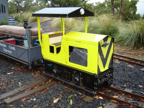
The voltage control unit is used to power the field windings of the alternator, which generally only draw 2~3 amps depending on the particular alternator. The more voltage that is applied to the field windings the more main output power the alternator will produce. It really is that simple. What I am effectively doing is replacing the alternator's voltage regulator with a variable voltage control unit. Either an electronic type, or just a series of resistors controlled by a rotary switch, can be used, and this is used to control the alternator field current from 0 to 12 volts. This in turn controls the main alternator output which controls the traction power and speed.
The positive output of the voltage control unit needs to be connected to one of the alternator brushes with the other brush connected to negative or earth. It doesn't mater which brush is connected to the positive feed and which is connected to the negative or earth. This is a simple task with alternators fitted with an external regulator as the regulator is simply disconnected. Alternators with an internal regulator, which is common in modern units, must have the internal regulator disconnected or removed. In some alternators, the brushes are held in position by the regulator itself. In this case the regulator needs to be disabled but left it in place to hold the brushes in position. Newer types of alternators are generally better suited because they tend to have much higher outputs than the older types of the same physical size. They also have the added bonus of having an internal cooling fan rather than the external fan like the older alternators which means one less thing spinning around inside the loco to get fingers caught in!
The voltage control unit and the rest of the loco electrical system are powered by a 12 volt car battery. When possible, a second alternator is fitted to charge this battery as the traction alternator can no longer be used to charge the battery. Some electric start engines have an inbuilt charging system for charging the starting battery but this will only charge when the engine is running at full revs which I find annoying because running flat out, they just sound like an old lawn mower!
In my smaller loco, I simply don't have the space for a second alternator to charge the battery so I just charge it with a battery charger when required. Because of the low amount of power that is required to power the alternator field windings, I find that I only need to charge the battery every 3 to 4 running days.
My first setup used a 5 position rotary switch driving a series of relays which in turn switched a series of ignition coil ballast resistors. Refer to Fig. 03 below for circuit details. This is an almost identical circuit to a Resistive Speed Controller, except the resistor values need to be re-calculated for the alternator field current. This circuit powered the alternator field windings in 5 voltage steps or notches. The ballast resistors were later replaced with a rheostat as shown in Fig. 04, and then later the whole setup was replaced with the simple electronic control described below.
The rotary switch was used along with a "dead man's" button to switch the relays so only the small current of the relay coil was being switched by the rotary switch. Each relay bypassed one resistor out of the circuit so that the further the rotary switch was turned, the less resistors the power had to flow through before reaching the alternator field windings. Less resistors meaning more power to the field windings therefore more power out of the alternators main output. The system worked like this:
If the first speed or notch voltage was found to be too high causing the loco to lurch forward when the dead man's button was pressed, then another resistor or two were added in series to reduce the voltage to the field windings. The aim is to reduce the voltage in the field windings enough so that when the dead man's button is pressed with the rotary switch in the first notch, the alternator is only putting out just enough power to get the loco just creeping away from a stand still. If starting up a hill or with a big load and the first speed or notch does not have enough power to start the loco moving, then it is just a matter of clicking it up another notch. As long as the last notch on the rotary switch has a full 12 volts running from the battery directly to the field windings and not through any resistors, then the alternator will be supplying full power to the traction motor(s).
Unless the rotary switch is capable of handling at least the current draw from the alternators field windings, it is necessary for the rotary switch to drive a relay for each notch so the power running from the battery, through the resistors, and then to the field windings, is not actually running through the rotary switch itself. The common automotive type relays from an auto parts suppliers are used for this.
When building my next loco, I was after a simpler approach. A fellow club member gave me a circuit diagram for a simple electronic voltage control unit that he had made for his own loco. The electronic unit is used directly in place of the rotary switch controller described above, again having the positive output from the control connected to one of the alternator brushes. The electronic voltage control unit saves a lot of the extra wiring that is involved with the relays and resistors used by the rotary switch controller and has the added bonus of having a smoother control over the loco power and speed. This was by far a better setup than my first loco fitted with the rotary switch control so I converted it over to the electronic control so all of my locos have the same control system.
When fitting the electronic control unit, it is important to use an inverse parallel diode across the field coil to protect the controller transistors from any voltage spikes. The diode should be rated at a higher current than the current draw from the field windings, and mounted as close to the alternator as possible. Also, the 2N3055 power transistor needs to be fitted to a reasonably large heat sink.
Shown below in Fig. 05 is the basic circuit diagram for my locos. Fig. 06 shows the details of the simple voltage control unit that I now use. With only one resistor, two transistors and a 5K potentiometer, it is clear to see that it is a very simple yet very effective control. Many thanks to Graeme Reardon for the circuit diagram of the voltage control unit. As can be seen in the diagram, I separate the 5K pot from the circuit, fit the transistors into a small enclosure in the loco, and fit the 5K pot into the hand control. An alternative to using either the rotary switch control or the simple voltage control unit described above would be to use one of the 12 volt (10A) speed control kits which are available from most electronics hobby stores.
|
|
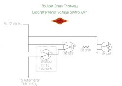 Click to enlarge Reardon's voltage control unit (Used with permission) |
The B+ 12 volt input at the top left of the loco wiring diagram is taken from the battery which can be a stand alone battery or can be charged via a second alternator onboard the loco. All negative or earth terminations are connected to the loco chassis. The 14 pin plug is the plug where the hand control connects to the loco. I use military style 14 pin plugs as they are very robust and the pins are large enough that they are able to be fitted with 3mm (10 amp) automotive wire. When fitting a second plug to the front of a loco, the #8 and #9 wires need to be reversed on the front 14 pin plug. This ensures that which ever direction is selected on the direction control switch, the "train" moves in the correct direction regardless of wether the loco is connected to the train running forwards or backwards (in the cab forward or cab trailing direction).
I have not shown any details of the main FWD/REV relay as this will differ depending on the traction motor(s) and relays used. My smaller loco uses a 3 terminal traction motor with one positive input for each direction and a common negative or earth terminal. The larger locos on the other hand all have 4 terminal traction motors with a completely different FWD/REV relay. (See Controller article for reversing details of different motor configurations)
In the interests of keeping the diagram clear and simple, various other functions of the diagram have been omitted for clarity. I have wired other pins for ancilliary functions, and the full connections are:
| Pin # | Function |
|---|---|
| 1 | Spare |
| 2 | Engine start |
| 3 | Engine stop |
| 4 | Compressor |
| 5 | Horn |
| 6 | Light |
| 7 | Dead man |
| 8 [*] | Forward (No.1 end) |
| 9 [*] | Reverse (No.1 end) |
| 10 | Field voltage input |
| 11 | B+ to controller |
| 12 | Spare |
| 13 | Spare |
| 14 | Earth (chassis) |
| * Pins 8 & 9 reversed on No.2 end | |
Either of the above controls can be used with any number of traction motors as long as the traction alternator has enough main output capacity to power the traction motor(s), and the driving engine has enough power to drive the alternator. It is possible to stall the driving engine with too much load on the alternator. I prefer to fit a larger engine that is actually required to drive the alternator and then run it at only part throttle to avoid the "lawn mower running flat out" sound effect!
I have found that a 5.5 HP engine is capable of running an alternator of around 100A output capacity, but without the additional alternator for charging the battery. This is close to the limit though while running at only part throttle. My larger locos use a 13 HP engine driving a 160 amp traction alternator and one of them is also fitted with an additional 40A auxiliary alternator for charging the battery. This is much more suitable as the 13 HP engine has ample power to run at part throttle and still drive both the main traction and auxiliary alternators.
Regardless of which control system is used, it is vitally important that the field relay (operated via the dead man's button) can only be powered while the main reversing relay is closed in either the forward or reverse direction. The winch relays that I use can be in the 'neutral' position meaning there is no circuit from the main alternator output to the traction motor. When the alternator field is powered up by the voltage control unit, the main output will be producing power. If the main reversing relay is in the 'neutral' position then there is no circuit from the alternator main output to the traction motor. The power being produced by the alternator has nowhere to go, the result being that the rectifier diodes in the alternator are destroyed instantly!
I avoid this by taking the positive feed to the dead man's button (which powers the field relay) from the FWD/REV switch as can be seen in the loco wiring diagram above Fig. 05. I achieve this by linking the two terminals on each end of the DPDT direction control switch and feed 12 volts into the centre terminal on only one side. This is then fed out to the dead man's button from the centre terminal on the other side but ONLY when either FWD or REV is selected. Fig. 07 below shows a picture of the DPDT direction control switch and how it is wired.
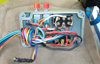
The main 12V input is to the lower middle pin seen with 2 red wires and 1 white wire soldered to it. From there the 12V is directed through the FWD wire link (dark green) or the REV wire link (mid blue) when either FWD or REV is selected. Note that these wires are linked across both the upper and lower terminal on the end of the switch. This is so the 12V input feed from the bottom middle terminal is only fed out through the top middle pin (single white wire) via the linked terminals when either FWD or REV is selected. The white output wire is the "switched" 12V feed to the dead man's button seen on the left.
It should be noted that with the full 12V applied to the alternator field windings, the alternator output voltage can be much higher than the normal 12V. The output can reach 40V to 50V, or even more, so the traction motors need to be able to handle the higher voltage (and the resulting higher speed) which is why I use 24V traction motors. Normally in a car, the voltage regulator takes care of the output voltage, but now with a separate field supply, the output can vary over a much wider range. Most DC motors will run at a higher voltage, and the 24V motors I use happily run at the increased voltages.
The relays I use for the general wiring are the common 12V automotive type relays. I use these as they as reliable, cheap, readily available. They are also available in N/O and N/O - N/C configuration which is often handy. I have used relays to operate all functions on the loco so there is very little current draw through the 14 pin hand controller plug or the wiring to the hand control. Also because when used in M/U (Multiple Unit) configuration, the one control is only powering multiple relays and not powering multiple heavy current loads in each connected loco. I always use 3mm (10A) automotive wire for the general wiring and heavy cable, more like battery cable to wire the traction motors.
Another thing to note when using very late model alternators is the maximum rectifier diode voltage rating. As stated above, the output can reach 40V to 50V, or even more from the modified alternator and the rectifier diodes MUST be rated at a higher voltage than this or they will be destroyed instantly rendering the alternator useless. Unfortunately I found this out the hard way as I recently fitted a brand new alternator to a loco for a friend. It was a 90A alternator from a late model vehicle. I removed the regulator and wired it up to the controller. A quick test proved everything to be working properly.
The following weekend's running day was the first time the owner had driven the loco with the new alternator fitted and after a couple of laps, he commented on how well it was performing. Unfortunately not 30 seconds later it died and was showing the symptoms of a blown rectifier diode. That being, the alternator getting hot quickly and very little available power output from the alternator even though the alternator was loading the driving engine heavily, even to the point of stalling the engine! Upon stripping the alternator, it was discovered that the rectifier diodes in this particular alternator were designed to short circuit (permanently) if the voltage peaked above 26V. The theory behind this is that if a fault in the alternator causes a severe voltage spike, the diode will blow protecting the cars ECU. A good safety feature if protecting an ECU is the objective, but not much help in this application!
A recent discovery is that all later model 12 volt Bosch alternators (the ones fitted with internal cooling fans) have diodes that are rated at only 26 volts. This makes then unsuitable for use as a traction power source without first either swapping the rectifier diodes with higher voltage rated replacements, or bypassing the originals and fitting an external rectifier. Using an alternator already fitted with suitable diodes (100 volts or higher) is by far a better option.
I am often asked what diameter pulleys are required for this setup. The answer to that is somewhat dependant on the engine driving the alternator. In the normal automotive application the engine RPM varies considerably, but is in the range of 1000 RPM to 3000 RPM most of the time, with the alternator typically rotating at around 1800~5500 RPM. As most single cylinder Honda style engines used for miniature locomotive application run at 1000~3500 RPM, an engine to alternator pulley ratio of around 1.8:1 to 2.5:1 is desirable so the alternator is operating within its normal operating speed. The actual ratio will depend to some extent on the amount of space available. I always use the standard alternator pulley and fit the appropriate size vee belt pulley to the driving engine. Pulleys with a taper lock hub are the best choice and are available from most industrial bearing suppliers.
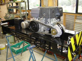
As mentioned above, I always try to fit my locos with a larger engine that what is required to drive the alternator/s so I can run them a lot slower than full power output speed. They are a lot quieter and sound more realistic running at only part throttle. There's nothing more annoying or unrealistic than a perfectly built miniature loco that sounds like an old lawn mower screaming its head off! If a larger engine is used (and run at a slower speed) then a slightly higher engine to alternator pulley ratio should be used to keep the alternator speed up.
While on the subject of 4 stroke Honda style engines, I have found that solid mounting the engines seems to be much better than mounting them on flexible engine mounts. I find that if they are able to move on flexible mounts then that's exactly what they will do. If solidly mounted to a heavy loco, they tend not to vibrate much at all as the mass of the loco absorbs the movement. Also, if an engine is rubber mounted then it needs to be rubber mounted on a frame which the alternator is also mounted to meaning both the engine and alternator are vibrating away on the rubber mounts. If the engine is rubber mounted and the alternator is solid mounted to the loco frame, the tension on the vee belt between the engine and alternator will pull on the rubber engine mounts and eventually break them.
So there you have it. A simple alternator modification to provide a variable power source for miniature loco traction motors.
Be sure to check out the locos described above, along with lots of other great pictures and info on the Boulder Creek Tramway website.
Now for some calculations to work out what size alternators, motors, engines etc are needed. The relationships between voltage, current etc and electrical calculations are quite simple, but probably power (P = E * I) is the most useful here. Another useful factor is 1 HP = 746 Watts (W).
Assume a loco has two 12V 20A traction motors. The power required for each motor is 12 * 20 = 240W, or 480W total. Allowing for a little extra, an alternator with around 600W (=50A) of output will be required. To determine the alternator output in Watts, the amp rating is multiplied by the volts : 50A x 12V = 600W. Allowing for mechanical losses, the output from the petrol engine will need to be more than 600 Watts to drive the 50 amp alternator. There are always mechanical losses in the bearings, power loss for cooling fans, losses in the drive belts etc, and there are conversion losses in the alternators and motors as well. Conversion losses are say 15%, and drive losses are say 20%, so total losses are up to 35% of output power. If the alternator requires 600W to drive it, the engine needs to be at least 925W power (or 1.25HP) or more to allow for the above losses. Remember also that the Horsepower rating of an engine is generally its rating running at full revs, so a 3HP to 3.5HP engine would be a more realistic choice for the 50A alternator. For a 100A alternator, a 5~6.5HP engine would do the job. In this application, bigger is always better!!! But don't overdo it!
|
Updated: 19 Feb 2016 108 Now viewing: 1 |
Text and photos Copyright © 2008-2019 Dave Webb, All rights reserved. |
Created by deeja Nov 09